
Side-action tooling components
Injection Mold Slider Machining
Injection mold slider RFQs should state travel, angle pin or cam drive, shutoff faces, wear pairs, and heat-treat condition before quoting.
Short answer
An injection mold slider is a side-action component that moves out of the way so an undercut can release before ejection. A slider can be machined correctly to its own drawing and still bind, flash, or wear early in the tool, so the RFQ has to describe how it moves, what it seals against, and which surfaces slide on which.
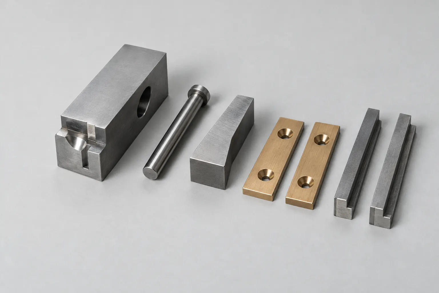
Sliders are quoted as single parts but behave as assemblies. The slider body, its angle pin or hydraulic drive, the heel or wedge that locks it, the guide rails or gibs, and the wear plate under it all share the same clearances. A replacement slider that ignores the worn condition of its mating parts is a common reason a repaired tool still flashes. Injection mold slider design decisions such as travel, lock angle, and shutoff geometry should therefore arrive with the RFQ rather than be inferred from one component drawing.
Applicability
Injection Mold Slider Machining use cases
New sliders for side cores, side holes, or external undercuts where the tool design is complete and the slider drawing is released.
Replacement sliders for an existing tool, where the fit to worn guides, heels, and wear plates decides whether the part works.
Slider sets that include the body, insert, heel or wedge lock, gibs, and wear plates and should be quoted and checked together.
Sliders with molding inserts, cooling channels, or textured or polished molding faces that add EDM, grinding, or polishing steps.
RFQ inputs
RFQ inputs and drawing requirements
Tool and motion context
State the slider travel, the drive method (angle pin, cam, spring, or hydraulic cylinder), and the lock angle of the heel or wedge relative to the angle pin.
Molding and shutoff faces
Mark the surfaces that form plastic, the shutoff faces against the core or cavity, and any surface that must be fitted or spotted at assembly.
Sliding pairs and wear materials
Identify which faces slide on guide rails, gibs, or wear plates, the material and hardness of each pair, and any bronze or coated wear surfaces.
Material and heat treatment
Give the steel grade, hardness target, and whether the slider is roughed before heat treatment and finished by grinding or EDM afterwards.
Replacement evidence
For a repair, send the original drawing revision, measurements of the worn mating parts, and notes on how the old slider failed.
Constraints
Constraints and quote assumptions
- A slider drawing alone does not define its running clearance; the guides, heel, and wear plate it works against have to be known or supplied.
- Shutoff faces usually need fitting at the tool, so the quote should say whether parts ship to drawing size or with fitting stock left on.
- Hardened sliders with molding detail often need grinding and EDM after heat treatment, which changes lead time more than the rough machining does.
- Cooling channels inside a moving slider need their connection method and sealing defined, or they become an assembly problem at the mold shop.
Related manufacturing examples
Related manufacturing references

Precision Slide Block
Precision Slide Block shows the guided sliding faces and locating features that set slider clearance in the tool.
Review reference
Bronze Wear Plate
Bronze Wear Plate is typical of the wear surface a slider runs on, where material pairing matters as much as flatness.
Review reference
Matched Wear Plates
Matched Wear Plates illustrate parts that should be inspected as a pair because the slider sees both at once.
Review reference
Drilled Guide Rail
Drilled Guide Rail is the kind of guide component that controls slider travel and should be quoted with the slider when it is worn.
Review referenceRelated pages
Continue the RFQ review
Precision injection mold components
The main service page for inserts, cores, and other drawing-controlled tooling components.
Open pageInjection mold lifters
Use the lifter guide when the undercut is internal and released by the ejector system.
Open pageWire EDM machining
Hardened sliders with fine molding detail often finish on wire or sinker EDM after heat treatment.
Open pageUndercut machining guide
Machined undercuts are an access problem rather than an ejection problem; this guide covers how they are cut.
Open pageFAQ
Injection Mold Slider Machining FAQs
What is the difference between a slider and a lifter in an injection mold?
A slider moves sideways on the parting line, usually driven by an angle pin or cylinder as the mold opens, and suits external undercuts and side holes. A lifter is mounted on the ejector system and moves at an angle as the part is ejected, which suits internal undercuts that a slider cannot reach.
Should the angle pin, heel, and wear plates be quoted with the slider?
When the slider is new or the tool has worn significantly, yes. Those parts set the slider position and clearance, so quoting them together lets the fit be checked as a set instead of hoping a new slider matches old mating parts.
Can a replacement slider be made from the worn part?
The worn part helps, but it shows the geometry after wear, not the design intent. The original drawing, or a reverse-engineered drawing that the buyer approves, should control the order, with the worn part used only to confirm features and the mating condition.
Side-action tooling components
Quote the slider with the parts it runs against.
Send the slider drawing, the drive and lock details, the mating guide and wear-plate drawings, and the steel and hardness for each part.
Start slider RFQ