
Internal undercut release
Injection Mold Lifter Machining
Injection mold lifter RFQs should state lifter angle, ejector stroke, guide bushing, shutoff faces, and material pairing before quoting.
Short answer
An injection mold lifter is an angled component driven by the ejector plate that moves sideways as it rises, releasing an internal undercut that a slider cannot reach. Lifters fail through galling, binding, and flash at the molding head, so the RFQ needs the angle, stroke, guide arrangement, and material pairing, not only the lifter outline.
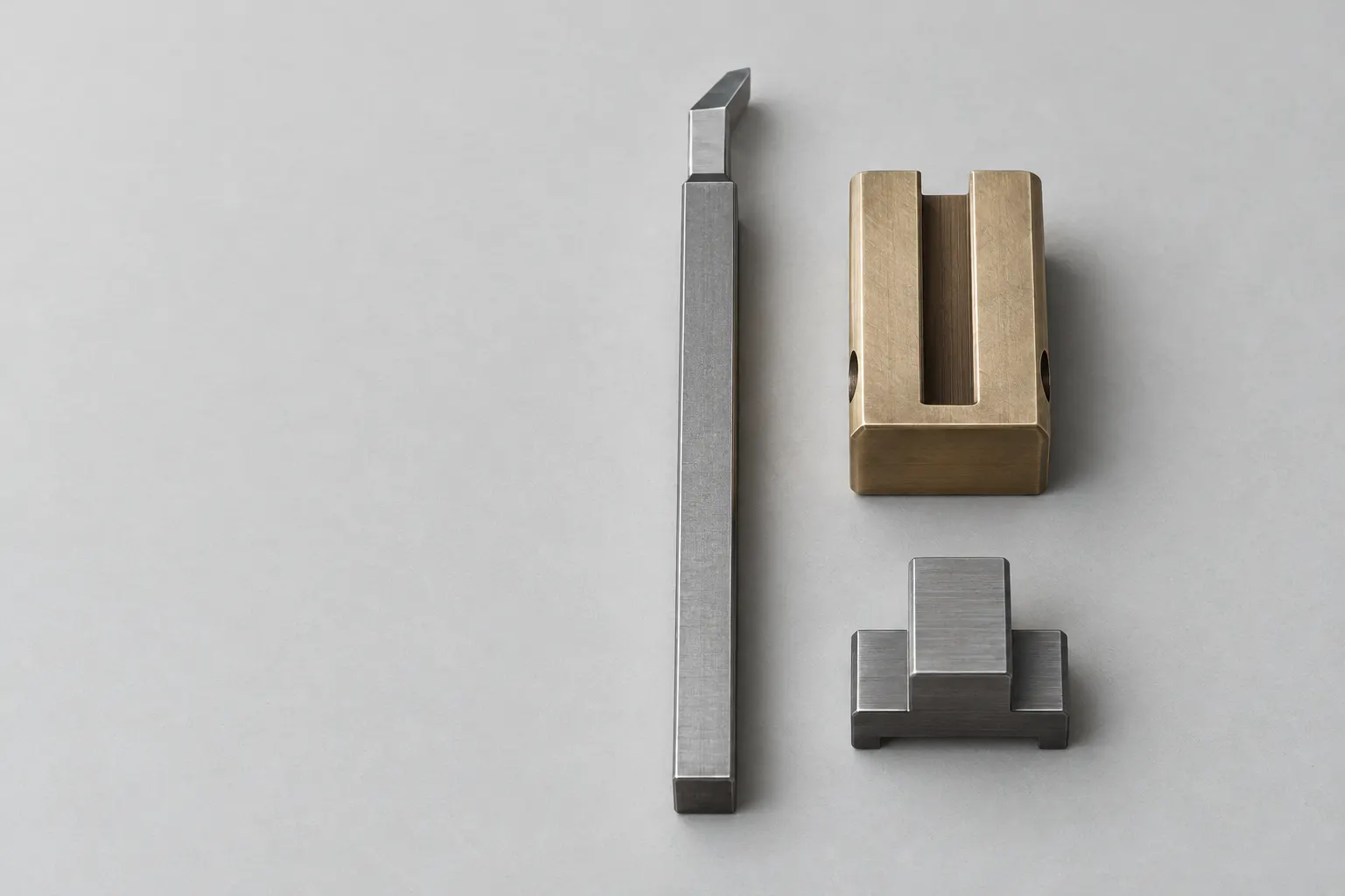
A lifter rod, its molding head, the guide bushing or wear block it slides through, and the base or slide that couples it to the ejector plate all have to agree on one angle and one stroke. Injection mold lifter design is usually fixed by the toolmaker, but the machining RFQ still has to carry that intent. Lifters are long, angled, and often hardened, so straightness, the angle of the rod relative to the molding face, and the finish of the sliding surfaces deserve explicit callouts.
Applicability
Injection Mold Lifter Machining use cases
Lifters that release internal undercuts such as snap hooks, internal ribs, or inward clips on molded parts.
Replacement lifters for tools where the original lifter galled, cracked, or wore and the guide bushing condition is known.
Lifter sets that include the rod, molding head, guide bushing or wear block, and ejector-plate coupling and should be checked together.
Lifters with molding detail, texture, or polish on the head that need EDM or polishing after hardening.
RFQ inputs
RFQ inputs and drawing requirements
Angle and stroke
State the lifter angle, the ejector stroke, and the resulting lateral movement so the angle can be checked against the undercut depth.
Guide arrangement
Identify the guide bushing or wear block, its material, and the running clearance the tool design expects between rod and guide.
Ejector-plate coupling
Describe how the lifter base attaches and slides on the ejector plate, including any T-slot, gib, or roller detail.
Molding head and shutoffs
Mark the molding surfaces, shutoff faces against the core, texture or polish requirements, and any fitting stock to leave on.
Material and surface treatment
Give the rod and head steel, hardness, and any nitriding or coating, together with the material of the guide it runs against.
Constraints
Constraints and quote assumptions
- Long angled lifter rods are sensitive to straightness after heat treatment, so the drawing should state where straightness and angle are measured.
- Galling is a material-pairing problem as much as a finish problem; identical hardened steels sliding on each other need to be called out and reviewed.
- The molding head often needs fitting against the core at assembly, which should be reflected in the delivered size and the inspection plan.
- A lifter quoted without its guide bushing assumes the existing bushing is still in tolerance, and that assumption should be confirmed by the buyer.
Related manufacturing examples
Related manufacturing references

Drilled Guide Rail
Drilled Guide Rail represents the guide components that set lifter alignment and should be reviewed with the lifter.
Review reference
Serrated Wear Strip
Serrated Wear Strip shows the wear surfaces involved when sliding tooling parts need defined material pairing.
Review reference
Machined Cavity Block
Machined Cavity Block is the kind of core-side detail a lifter head shuts off against at the parting line.
Review reference
Bronze Wear Plate
Bronze Wear Plate illustrates the dissimilar wear material often used to stop hardened sliding parts from galling.
Review referenceRelated pages
Continue the RFQ review
Precision injection mold components
The main service page for inserts, cores, and other drawing-controlled tooling components.
Open pageInjection mold sliders
Use the slider guide when the undercut is external and released on the parting line.
Open pageCustom core pins and ejector pins
For non-standard pins that sit in the same ejector system as the lifter.
Open pageFAQ
Injection Mold Lifter Machining FAQs
Why do injection mold lifters gall or seize?
Usually because the rod and its guide are too similar in material and hardness, the clearance is wrong for the operating temperature, lubrication is poor, or the angle and stroke load the rod sideways. A material pair with different hardness or a bronze or coated guide is a common answer, and it has to be specified at the RFQ stage.
Should a lifter be quoted as one part or as a set?
Quote it as a set when the guide bushing or wear block is also worn, or when the lifter is new. The rod angle, guide bore, and ejector-plate coupling decide whether it runs freely, so checking them together avoids fitting work at the mold shop.
What should be inspected on a finished lifter?
The lifter angle relative to the base, rod straightness, the size and finish of the sliding surfaces, the molding-head geometry against its datums, and hardness. If the head is to be fitted at assembly, the report should state the stock left on it.
Internal undercut release
Quote the lifter with its angle, stroke, and guide.
Send the lifter drawing, the ejector stroke and angle, the guide bushing or wear block details, and the material and hardness of each sliding pair.
Start lifter RFQ